The 4 x 4 matrix keypad usually is used as input in a project. It has 16 keys in total, which means the same input values. The 4 x 4 Matrix Keypad Module is a matrix non-encoded keypad consisting of 16 keys in parallel. The keys of each row and column are connected through the pins outside pin R1-R4 as labeled beside control the rows, when L1-L4, the columns.
A 4×4 matrix keypad consisting of microswitch buttons. The module has four holes 3mm (M3) holes for mounting. The pin designations on each PCB are shown on each PCB. Four pins are thus used as an x coordinate and the other 4 as a y coordinate.
The module is already equipped with soldered pin headers (rotated 90 degrees).
How it Works:
First test whether any key is pressed down. Connect power to rows, so they are High level. Then set all the rows R1-R4 as Low and then detect the status of the columns. Any column of Low indicates there is key pressing and that the key is among the 4 keys of the column. If all columns are High, it means no key is pressed down. Next, locate the key. Since the column in which the pressed key lies is identified, knowing the line would finalize the testing. Thus, set the rows as Low in turns until any is unveiled accordingly other rows will still be High.
Now the row can be identified. Detect the status of each column in turns. The column tested Low is the one intersecting with the line their cross point is just the key pressed.
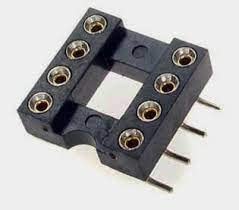
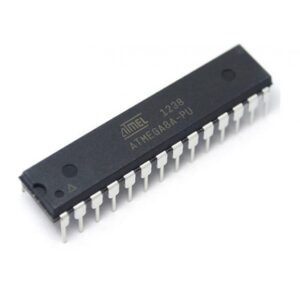 ATMEGA-8A PU DIP-28 Microcontroller
1 × ₹150.00
ATMEGA-8A PU DIP-28 Microcontroller
1 × ₹150.00 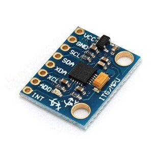 GY-521 Mpu6050 Module+ 3 Accelerometer for Arduino AB0073
1 × ₹274.97
GY-521 Mpu6050 Module+ 3 Accelerometer for Arduino AB0073
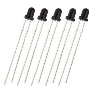
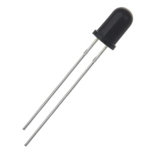
1 × ₹274.97 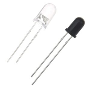 100pair 5mm 940nm 100pcs IR Receiver + 100pcs IR Emitter Transmitter LED Diode Lights Clear Infrared DC 1.2V 30mA for DIY Projects AB0089
1 × ₹700.00
100pair 5mm 940nm 100pcs IR Receiver + 100pcs IR Emitter Transmitter LED Diode Lights Clear Infrared DC 1.2V 30mA for DIY Projects AB0089
1 × ₹700.00 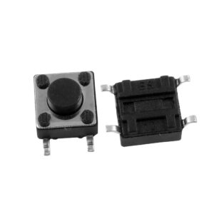 Imported 100 Pcs SMD 4 Pins Push Button Momentary Tactile Switch 6x6x5mm AB0179
1 × ₹710.00
Imported 100 Pcs SMD 4 Pins Push Button Momentary Tactile Switch 6x6x5mm AB0179
1 × ₹710.00