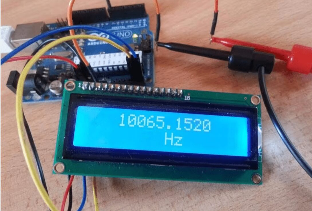
Arduino Frequency Counter Kit with 16×2 LCD Display
SKU:Model number: GM1602A
Resolution: 16*2
Operating temperature: -20 to 70℃
Pins: 16
Display Size: 1602
₹1,262.60 ₹2,000.00

Arduino Frequency Counter Kit with 16×2 LCD Display
Frequency Counter, as the name indicates, is an electronic device or component, which is used to measure the frequency of a signal. In case of a repetitive electronic signal, a frequency counter measures the number of pulses in that signal.
We generally use an oscilloscope to depict the signal, calculate the time period of the signal and finally convert it to calculate the frequency of the signal. But, oscilloscopes are very expensive and everyone cannot afford it.
Hence, a simple Digital Frequency Counter can be built which might come in handy to measure the frequency of a clock signal, for example.
In this project, an Arduino based Digital Frequency Counter is designed to measure the frequency of an incoming signal.
Circuit Diagram: –
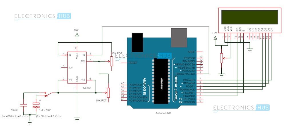
Arduino Frequency Counter Circuit Diagram
Components
Arduino Part
(AI0001) Arduino UNO
(AI0006) 16 X 2 LCD Display
(AI0046) Prototyping Board
(AI0380) Connecting wire
Signal Generator Part
(AI0173) NE555 Timer IC
(AI0174) 10 KΩ Potentiometer x 1
(AI0869) 100 nF Capacitor (Code: 104)
(AI0868) 1 µF / 16V Electrolytic Capacitor
(AI0082) 5V Power Supply (12V is not suitable as it might damage Arduino board).
Circuit Design
The design of the Frequency Counter using Arduino UNO can be divided in to two parts: The Arduino part, where the processing of the signal’s information takes place and the Signal Generator part, where the signal whose frequency to be measured is generated.
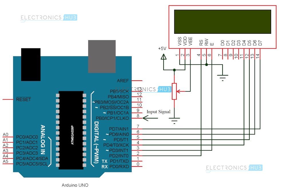
Arduino Circuit
Arduino part of the project consists of Arduino UNO board and a 16 X 2 LCD Display. Pins 1 and 2 of the LCD (Vss and Vdd) are connected to ground and 5V supply respectively. Pin 3 (Vee), which is used to adjust the contrast of the display, is connected a Potentiometer.
Pins 4 and 6 (RS and E) of the LCD are connected to digital I/O Pins 2 and 3 of the Arduino. Pin 5 (RW) of the LCD is connected to ground.
Pins 11 to 14 (D4 to D7) i.e. the data pins of the LCD are connected to the digital I/O pins 4 to 7 of Arduino. Pins 15 and 16 of the LCD are supply pins of the backlight LEDs and are connected to ground and 5V (Pin 16 to 5V through a 1KΩ resistor) respectively.
Features
6 characters wide, 2 rows
White text on the yellow background
Single LED backlight included can be dimmed easily with a resistor or PWM.
Can be fully controlled with only 6 digital lines! (Any analog/digital pins can be used)
Specification
| Model | JHD 16×2 |
|---|---|
| Characters | 16 |
| Character Color | White |
| Backlight | Blue |
| Input Voltage (V) | 5 |
| Length (mm): | 80 |
| Width (mm): | 36 |
| Height (mm): | 14.5 |
| Weight (g): | 30 |
Applications
A simple frequency counter, using simple components is designed that can be used to measure the frequency of a pulse without the need of an oscilloscope.
Multiple ranges of frequencies can be measured by selecting suitable components.
Frequencies of all types of test signals can be calculated by adding a Schmitt Trigger between the generated signal and Arduino.
Arduino Frequency Counter Kit with 16×2 LCD Display Overview
The Arduino Frequency Counter Kit with 16×2 LCD Display (Model GM1602A) is a compact, Arduino-based instrument designed to measure the frequency of repetitive electronic signals. Its built-in 16×2 alphanumeric LCD provides real-time pulse count readouts, making it ideal for hobbyists, students, and electronics technicians.
Key Features of Arduino Frequency Counter Kit with 16×2 LCD Display
- 16×2 LCD module (1602 resolution) for clear frequency display
- Arduino-based design with 16 I/O pins for easy interfacing
- Operating temperature range from –20 °C to 70 °C for versatile use
- Model GM1602A PCB assembly for reliable signal measurement
- Accurate pulse counting for clock signals and square waves
- Genuine product, fast shipping from Zbotic within 24 hours
Applications and Use Cases
- Measuring clock frequencies in microcontroller and FPGA projects
- Verifying output of signal generators and oscillators
- Testing RF modules and simple radio circuits
- Educational labs for teaching digital electronics and timing
- Calibration checks for DIY waveform and function generators
How to Use Arduino Frequency Counter Kit with 16×2 LCD Display
Assemble the kit components onto the provided PCB, then connect a 5 V DC power supply to the VCC and GND terminals. Feed your input signal into the designated frequency input pin, and the onboard Arduino-compatible microcontroller will count pulses and update the 16×2 LCD in real time. No additional modules are required—simply power up and observe the display.
| Weight | 0.30 kg |
|---|---|
| Dimensions | 24 × 11 × 7 cm |
Related products
-
Uncategorized, Electronic Modules, Mechanical Parts & Workbench Tools, Workbench Tools
Portable Transistor Mini Spot Welding Machine Automatic
-30% Uncategorized, Electronic Modules, Mechanical Parts & Workbench Tools, Workbench Tools
Portable Transistor Mini Spot Welding Machine Automatic
The Portable Transistor Mini Spot Welding Machine Automatic is a compact, lightweight tool designed for precise, efficient spot welding. With automatic control for consistent results, adjustable settings, and a durable build, it’s perfect for small-scale welding tasks in workshops or repair settings. Ideal for welding materials like stainless steel, copper, and aluminum with ease.
SKU: n/a -
-
Uncategorized, Biometric/ ECG/ EMG Sensors, Sensor Mudules
ECG Module AD8232 Pulse Heart ECG Monitoring Sensor Kit
-68% Uncategorized, Biometric/ ECG/ EMG Sensors, Sensor Mudules
ECG Module AD8232 Pulse Heart ECG Monitoring Sensor Kit
Specifications:
- Sensor Type: AD8232 ECG Module
- Power Supply: 3.3V to 5V (DC)
- Output: Analog ECG signal output (can be read by microcontroller or ADC)
- Frequency Range: Typically 0.5 Hz to 40 Hz (filtered ECG signal)
- Connectivity: Standard header pins for easy connections to microcontrollers like Arduino
- Dimensions: Small, compact design for easy integration into various applications
- Compatibility: Works with platforms like Arduino, Raspberry Pi, and other microcontroller-based systems
Applications:
- Heart Rate Monitoring: Track your heart rate in real-time for personal fitness and health monitoring applications.
- ECG Data Collection: Collect electrical heart signals for health assessments, disease diagnosis, or medical research.
- Wearable Devices: Integrate the AD8232 module into wearable health devices such as smartwatches or fitness trackers for continuous monitoring.
- DIY Projects: Build your own ECG monitor or heart rate tracker for educational, experimental, or hobbyist purposes.
- Clinical Use: Implement in medical devices for patient monitoring, offering an affordable and compact solution for ECG data acquisition.
SKU: n/a